Thermal cycling testing is a very widely used especially in electronics. It exposes devices and components to fluctuating temperature, which causes fatigue in the components and especially in their interconnections. For example, cracking due to fatigue is one of the most common failure mechanisms in electronics, and therefore, it is a very important consideration in reliability analysis.
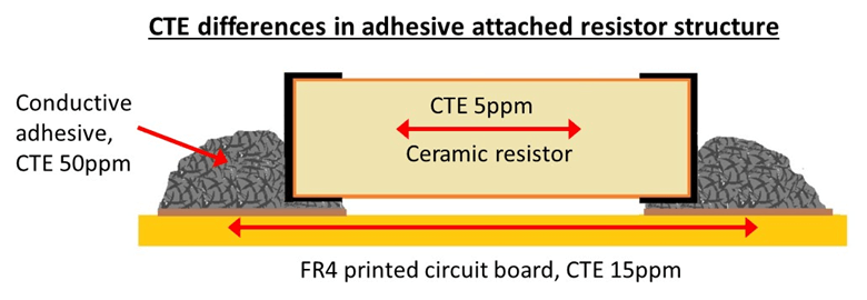
Fatigue failures are caused by different thermal expansion coefficients (CTE) of the materials used in electronics devices. For example, the CTE of silicon is very small (about 3ppm) while the CTE of polymer parts can be very high (more than 100ppm) especially, if the polymer materials need to be used unfilled. Even filled polymer materials tend to have rather high CTEs, as shown in the picture below, which can cause formation of very high stresses in the structures. Even though fluctuating stresses due CTE differences are the main reason for failures, in thermal cycling several other potential failure mechanisms are also present. For example, diffusion and relaxation of materials due to high temperature may affect the failure modes.
As mentioned above, thermal cycling testing is a very common test method. Due to this there are numerous test standards and recommendation for these tests and how they should be conducted. However, many standards give lots of options for test parameters or even mention that the parameters should be tailored according to the application. Although it is common to choose a test which has been widely used earlier, before testing it is useful to consider whether the parameters of the test really are suitable, or the most efficient ones for the studied component or device. There are several parameters to consider and picking the best combination is not straightforward.
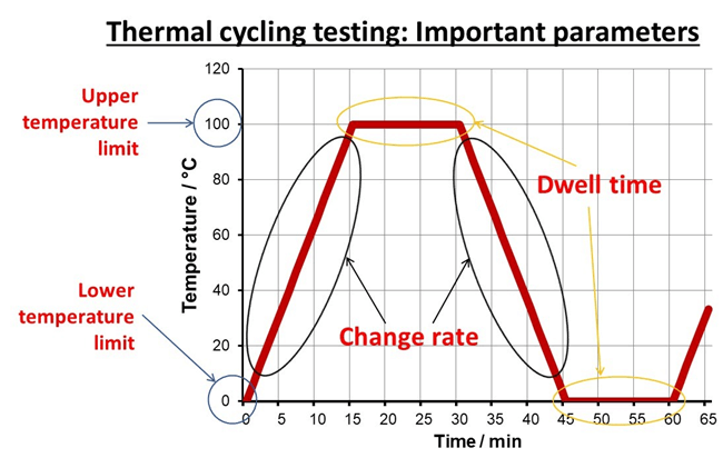
The main parameters of thermal cycling testing include temperature limits, dwell time at both limits and change rate between the limits.
The main parameters of thermal cycling testing include temperature limits, dwell time at both limits and the change rate between the limits. In the picture below the main test parameters are shown. All of them are important and affect the stresses formed during testing. Of course, the number of test cycles is also a critical factor and the duration of testing should always be carefully considered.
The temperature limits are critical for the acceleration level of testing. The greater the difference between the limits is, the higher the stresses caused by them will be. However, if the limits are too extreme, there is a marked risk that overstress failures occur, leading to early failures which would never really occur in use conditions. A typical example of a critical limit is the glass transition temperature, Tg, of polymer materials. A temperature limit above Tg may lead to catastrophic failure which is easily seen but it may also just change the failure mechanisms to unrealistic ones. Then again, it is useful to use as high temperature limit as possible, since, if the difference between the limits is not great enough, the test has very small acceleration factor and the test time becomes very long.
In addition to the stresses caused by the differences between the temperature limits, the exposure to either high or low temperature may cause degradation leading to failures. For example, high temperature accelerates many harmful processes including for example diffusion, migration, and oxidation. An example of such processes is the growth of intermetallic layers in solder joints which typically reduces the mechanical robustness of the joints. High temperature also causes degradation and oxidation of polymers and permanently weakens their properties. To take these factors into account, it is important to consider how long exposure time is suitable at each temperature limit i.e. the dwell time at each limit.
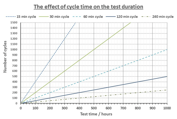
If a long dwell time is used, the test duration increases unless the number of cycles is reduced. In the picture below the effect of cycle time to the test duration is shown. If the aim is to do 500 cycles with a 30 min cycle, we need approximately 250h or 1.5 weeks of testing. With 120 min cycle the test time increases to 1,000h or to 6 weeks. Then again, sometimes long dwell time may even accelerate testing, if it causes changes in the structure which increase the stresses during the temperature changes. For example, at high temperature polymer materials relax or creep – the polymer chains in the material move to reduce the stresses caused by the high temperature. When the temperature is lowered, these changes may significantly increase the stresses formed in the structures. However, long enough dwell time is required for these changes to occur. Often it is difficult to optimize the dwell time, but it is good to consider if critical changes may occur at high temperatures and would an extended dwell time be required.
Futhermore, the change rate of the temperature is critical. Very fast cycling testing (or shock testing) may cause thermal gradients to form in the tested structures. This means that different parts of a device or component heat up at different rates and warping of the system may occur. If such rapid changes of temperature may occur at use conditions, it is important to test their effects. However, typically such shocks are not present and in testing they cause incorrect failure mechanisms. Consequently, it is typically better to use slower change rates which allows different materials to warm up at similar rate. However, slower change rate naturally increases the testing time. Maximum change rate depends greatly on the structure tested. Small structures or components warm quickly and can be normally tested with very fast change rates but large devices typically require slow change rates and, also longer dwell times should be used.
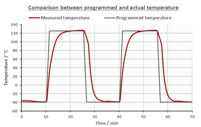
When the test profile has been chosen, it is good to remember that the actual temperature within the test chamber or more importantly within the tested component may be something quite different than the programmed temperature. In the picture below the test temperature measured from a tested component and the programmed profile are shown. As can be seen, the actual change rate is clearly slower than the programmed one causing the dwell time to be shorter. Due to this effect with large components, there is a substantial risk that the components do not reach the temperature limits especially when a short cycle time with a fast change rateis used. Therefore, it is useful regularly to measure what the test sample is really exposed to in the test conditions, and to adjust the test parameters if needed.
Finally, the number of cycles is a critical parameter to determine. It depends on several other parameters, for example on the test parameters, the use conditions, and expected use life. For some structures, such solder joints, several formulas to calculate optimal test durations exist. However, there is no easy answer how to determine the duration of the test and it should always be considered on basis of the tested components and structures.
Humidity testing is one the most commonly used accelerated reliability test methods. This makes sense since high humidity level is a one of the most common reasons to cause failures. Moreover, humidity testing is relatively easy to conduct and equipment for it is commonly available. A typical humidity test is a constant humidity test, in which tests samples are exposed to extended periods of steady high humidity conditions. Typically, high temperature is used as an additional accelerating factor, since this makes it possible to gain highly accelerating test conditions and, thereby, reduce the test time.
When humidity testing is planned it is important to choose suitable test conditions. This is not always easy since there are lots of test standards available and these standards give numerous different test combinations based on the test temperature, relative humidity (RH), and duration. In electronics it is quite common, that the same test is used repeatedly without really considering the suitability of the test. For example, a test with 85% relative humidity (RH) and 85°C, so called 85/85-test, has been very widely used as a basic test for almost everything in electronics, even though it is a very harsh test.
At least, when reliability testing for something new is developed or when an old design is markedly changed, the test methods should be carefully considered. Test parameters are even more important when acceleration factors are determined using several tests. In humidity testing this means that both test temperature and humidity level need to be considered.
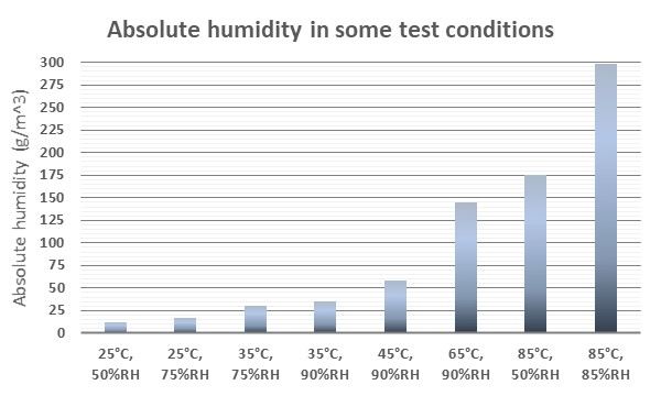
The level of humidity may be considered using absolute or relative humidity. The absolute humidity tells the actual amount of water in the air and is expressed in g/m3. The relative humidity tells the percentage of the maximum water the air can hold. Consequently, the relative humidity changes with temperature i.e. at low temperature smaller amount of water leads to higher relative humidity than at higher temperatures. In the figure below, the relation between the relative and absolute humidity is given at different temperatures. As can be seen, the absolute humidity can be very different at different temperatures, even though the relative humidity stays the same.
Absolute humidity can be very different at different temperatures, even though the relative humidity stays the same.
Typically, we use test standards and literary data to plan humidity tests. The standards give the humidity as relative humidity, most likely because it is much easier than to use absolute humidity. Moreover, the test chambers are programmed using relative humidity. The problem with relative humidity is that it easily leads to situation, in which one does not really realise how much the real amount of water changes between the tests and conditions. For example, if the use conditions have on average 35°C and 90%RH, it is very humid, but the absolute humidity is still only slightly more than tenth of the humidity in 85/85 test.
The problem with relative humidity is that it easily leads to situation, in which one does not really realise how much the real amount of water changes between the tests and conditions.
Below the absolute humidity of some common test conditions are compared. As can be seen, with increasing temperature the absolute humidity rises very quickly to very high values.
So why is this important? We are using more and more plastic or polymer materials in all engineering applications. Unlike metals and ceramics, polymers, and plastics tent to absorb moisture. For some polymers, this absorption can be considerable and for most polymers it depends on the amount of humidity present. So, if in test conditions the amount of water is significantly higher than anything possible in use conditions, there is a risk of accelerating failures which would never occur in the real conditions. One example of this is chemical degradation of polymers due to water such as hydrolysis, which may be accelerated hugely in high temperature and high humidity conditions but is not relevant in use conditions. Or the thermal and mechanical properties of a plastic part may considerable change due to high water content and again lead to failure which would not have happened in normal use conditions.
The challenge is that the combination of both high temperature and humidity is an excellent way to accelerate reliability testing. Especially, when the use life of a product is long, high acceleration is essential to reach reasonable testing times. Consequently, we must compromise with the extreme test conditions and the risks related to their use. However, before testing it is always important to consider the risks and is it meaningful to test with extremely high absolute humidity values. Sometimes, it is better to lower the temperature and humidity levels, even if this means longer testing.
Failure analysis process is used when something fails, and we need to know how and why it happened. The process itself may be very complex with numerous different analysis methods and tools. However, the overall process itself is typically quite simple and does not markedly change whether we are trying to figure out why a beer can has exploded (like the one in the picture above) or what happened to a complex electrical unit which has stopped working.
Commonly, the process can be described with four steps which you may need to repeat multiple times, especially with complicated failures which may involve several failure types.
Step 1. Data collection
The first part of the failure analysis process is the collection of data. The purpose of this part is to gather as much information as possible of the failure and of the factors related to it. Basically, this means verifying what has failed, how the failure happened or how it was observed, where did the failure occur, when did it happen, was the product used as it should be or has it been used at all, or anything else specific to the failure. In addition to the failure, it is important to gather as much information as possible of the failed device or structure. For example, what kind of materials, components, and manufacturing processes has been used.
Exploded beer can
Failure analysis often starts in a hurry, especially, if something critical has failed. Because of this, finding enough time to collect all necessary data can be a challenge. Furthermore, finding correct information can be quite difficult or even impossible. However, data collection is a crucial part of the process, because without enough data there is a major risk of that one uses unsuitable analysis methods or draws wrong conclusions.
Step 2. Hypothesis of the cause
After the data has been gathered, it will be used to make a guess of what could have happened. In addition to the collected data, we often need to use literary data, former experience, and history data from similar products to support our hypothesis.
Sometimes making such a hypothesis is very easy and just by using visual inspection we can see the probable cause for the failure. For example, there could be a crack which is clearly due to fatigue or obvious corrosion which has caused an electrical breakdown. However, it is common, especially in complex systems, that there are several possibilities and making a hypothesis of the cause is very difficult. It is even possible that we will start by eliminating potential causes just to get more information.
Even though making a hypothesis can be challenge, it is important since we can use it to move to the next stage i.e. we determine which analysis methods should be used.
Step 3. Analysis using various analytical methods
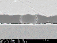
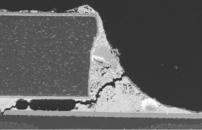
Preparation of cross-sections and their analysis with microscopic methods is often very effective way to analyse failures. However, cross-sectioning usually destroys the sample and therefore should be done only after other less destructive methods have been used.
The next stage of the process is to use suitable methods to analyse the failed product. There are lots of different methods we can use to do this. Some are quite straightforward and obvious, for example visual inspection is used to check what we are dealing with and in electrical systems some kind of electrical measurements are almost always used. However, often analysis methods are complex, require lots of experience and knowledge, and are expensive to use. Because of this, it is important to use the data from step 1 and the hypothesis from step 2 to decide which analysis methods to start with to ensure that they are both efficient and meaningful.
When the methods have been decided, the analysis should start with the least destructive methods. This way the failed samples are not destroyed and can be further analysed with other techniques if needed.
Moving to destructive techniques is often necessary after the non-destructive methods. This can be problematic, especially, if there is only one sample to analyse. It is possible that only one analysis can be conducted from the sample, since the analysis may fully destroy the sample. Consequently, it is vital to pick the right methods.
If you are unlucky, there are several failure mechanisms acting at the same time which can make the analysis very difficult. In such case you may just needs to make an educated guess and hope for the best. Sometimes it can also be useful to start by eliminating most of the potential causes and using the results to decide how to proceed.
Step 4. Analysis of the results and conclusions
After the data has been collected and the samples analysed, we analyse the results and draw conclusions i.e. determine what was the cause of the failure. Then we can write a report including all relevant data of the samples, description of used analysis techniques, results, and conclusions and the failure analysis process is complete.
However, in real world this might not be how the process goes. When we start to analyse the results or even before it, we can realise that we lack some critical data and we need to go back to step 1 to collect more information. Or the results given by various analytical methods are not conclusive and we need to use additional techniques and go back to step 3. Or the results indicate something unexpected, and we need to fix our hypothesis or maybe even start the whole process from the beginning. In practise this means that the failure analysis process often contains several cycles before it is finally concluded.
Finally, it is important to notice that more often than not there is considerable amount on uncertainty in the final results of the failure analysis even though it is well conducted. We can reduce the uncertainty by repeating the different parts – adding more analysis methods or even trying to replicate the failure mechanism. This can go on for a long time. Consequently, sometimes it is important to not only consider how to conduct the process but also to consider what is enough and when to stop it.
Soldering is the main technique for forming electrical interconnections. Here is a simple infographic of the main factors related to soldering process!
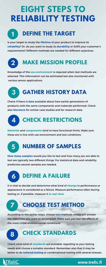
Selecting a suitable reliability testing method is not always simple. This guideline helps you to consider the most important aspects of test selection.
We use cookies to optimise our website and our service.
Functional
Always active
The technical storage or access is strictly necessary for the legitimate purpose of enabling the use of a specific service explicitly requested by the subscriber or user, or for the sole purpose of carrying out the transmission of a communication over an electronic communications network.
Preferences
The technical storage or access is necessary for the legitimate purpose of storing preferences that are not requested by the subscriber or user.
Statistics
The technical storage or access that is used exclusively for statistical purposes.The technical storage or access that is used exclusively for anonymous statistical purposes. Without a subpoena, voluntary compliance on the part of your Internet Service Provider, or additional records from a third party, information stored or retrieved for this purpose alone cannot usually be used to identify you.
Marketing
The technical storage or access is required to create user profiles to send advertising, or to track the user on a website or across several websites for similar marketing purposes.


Recent Comments